Inertial Measurement Unit (IMU)
Introduction to Inertial Measurement Unit (IMU) including MPU6050, MPU9250.
IMU - Inertial Measurement Unit (慣性量測單元)
慣性測量單元是測量物體三軸姿態角以及加速度的裝置。
一般一個IMU內會裝有三軸的陀螺儀和三個方向的加速度計,來測量物體在三維空間中的角速度和加速度,並以此解算出物體的姿態。
中科院雷射陀螺儀
 本院開發之新一代光電陀螺儀,具備以下優勢:
- 不具旋轉質量,可在高動態範圍環境下操作。
- 具極佳之偏差穩定性與重複性,大幅降低開機反應時間。
- 無磨耗元件,使維修容易。
- 可應用於不同領域的角度感測器,例如各種飛行器或航海器的導航、地面定位定向、與各式平台穩定控制。
Modern inertial measurement unit for spacecraft

Ring Laser Gyroscope
A ring laser gyroscope (RLG) consists of a ring laser having two independent counter-propagating resonant modes over the same path; the difference in the frequencies is used to detect rotation. It operates on the principle of the Sagnac effect which shifts the nulls of the internal standing wave pattern in response to angular rotation.

MEMS IMU

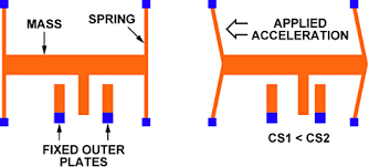
Accelerometer(加速計)
An accelerometer is a device that measures proper acceleration (“gravity force”).
an accelerometer at rest on the surface of the Earth will measure an acceleration g= 9.81 m/s2 straight upwards (測量加速度的裝置)

Gyroscope (陀螺儀)
A gyroscope is a device for measuring or maintaining orientation, based on the principles of angular momentum, it is to measure the rate of changes of the angles (deg/s)
(一種感測與維持方向的裝置,量測角速度)
 MEMS Gyroscope
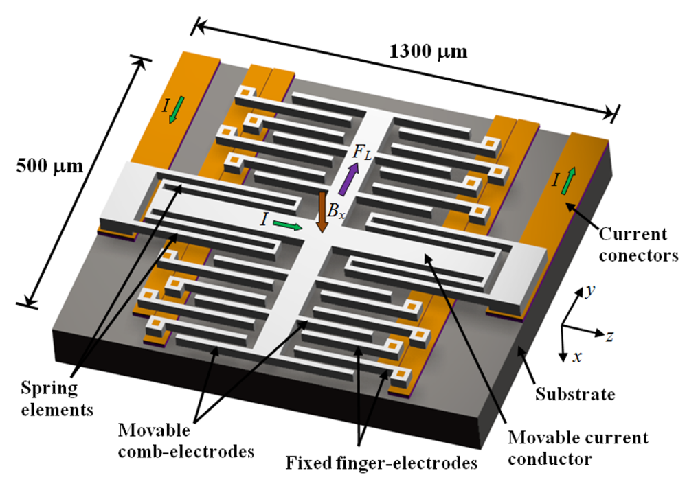
Magnetic Field Sensor (電子羅盤)
Resonant Magnetic Field Sensors Based On MEMS Technology
9-axis IMU(九軸慣性感測器)


Comparing Gyroscopes
ST ISM330DHC
Uncalibrated offsets are low, the one we grabbed had 0.006 rad/s (0.35 deg/s) max offset.
Datasheet’s Angular rate zero-rate level is typical ±1 deg/s.
No-motion observed noise was an incredibly low ±0.002 rad/s (±0.06 deg/sec) when running at 104 Hz and no filters on. Check the datasheet for more details!

LSM6DSOX
Uncalibrated offsets are low, the one we grabbed had 0.007 rad/s (0.42 deg/s) max offset.
Datasheet’s Angular rate zero-rate level is typical ±1 deg/s.
No-motion observed noise was an incredibly low ±0.003 rad/s (±0.17 deg/sec) when running at 104 Hz and no filters on. Check the datasheet for more details!

LSM6DS33
Uncalibrated offsets are fair, the one we grabbed had 0.034 rad/s (2 deg/s) max offset.
Datasheet’s Angular rate zero-rate level is typical ±10 deg/s!
No-motion observed noise was ±0.015 rad/s (±0.85 deg/sec) when running at 104 Hz and no filters on. Check the datasheet for more details!

LSM9DS1
Uncalibrated offsets are pretty good, the one we grabbed had 0.02 rad/s (1.2 deg/s) max offset.
Datasheet’s Angular rate zero-rate level is typical ±30 deg/s!
However, we noticed spikes of gyro data well outside the expected range. When those spikes are ignore, the no-motion observed noise was +- 0.007 rad/s (±0.4 deg/sec) at 1 KHz with the 408 Hz bandwidth filter on. Check the datasheet for more details!


MPU-6050
Uncalibrated offsets are fair, the one we grabbed had 0.04 rad/s (2.3 deg/s) max offset.
Datasheet’s Angular rate zero-rate level is typical ±20 deg/s!
No-motion observed noise was +- 0.05 rad/s (±0.29 deg/sec) with the 260 Hz bandwidth filter on. Check the datasheet for more details!

NXP FXAS21002
Uncalibrated offsets are pretty good - the one we grabbed had 0.01 rad/s (0.57 deg/s) max offset.
Datasheet’s Angular rate zero-rate level is typical post-mount ±50 LSB (NOT deg/s) - at 250 deg/s rate, that translates to ±0.4 deg/s
No-motion observed noise was +- 0.01 rad/s (±0.55 deg/sec) at 100 Hz output. Check the datasheet for more details!

ICM-20649
Uncalibrated offsets are not bad, the one we grabbed had 0.023 rad/s (1.3 deg/s) max offset.
Datasheet’s Angular rate zero-rate level is typical ±5 deg/s
No-motion observed noise was +- 0.015 rad/s (±0.86 deg/sec) at 1.1KHz. Check the datasheet for more details!

AHRS (Attitude and Heading Reference System)
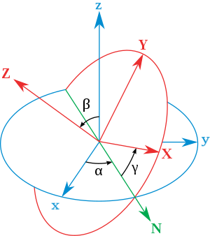
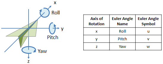
Euler Angles
Yaw Pitch Roll (YPR)

The coordinate system and rotation conventions

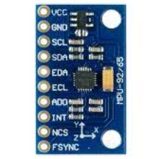
InvenSense MPU6050 & MPU9250
- MPU6050
MPU-6000 and MPU-6050 Product Specification Revision 3.4
MPU-6000 and MPU-6050 Register Map and Descriptions Revision 4.2

- MPU9250 Datasheet
- BNO080 Datasheet

Arduino Library: MPU6050


- Download Processing & Install
- Tools> add Tool> Library> Toxi
Sketchbook> IMU> MPU6050_DMP6_plane
- #define OUTPUT_TEAPOT

- click ./MPUplane/MPUPlane.pde
- modify port name:
String portName = "COM3"; - press Run

Sketchbook> IMU> MPU6050_DMP_Teapot

- click ./MPU6050Teapot/MPU6050Teapot.pde
- modify port name:
String portName = "COM3"; - press Run
Sketchbook> IMU>MPU6050_KalmanFilter
- Initialize IMU & get Acceleration
imu.initialize(); delay(100); imu.getAcceleration(&accX, &accY, &accZ); -
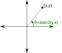
atan2

- Complementary Filter
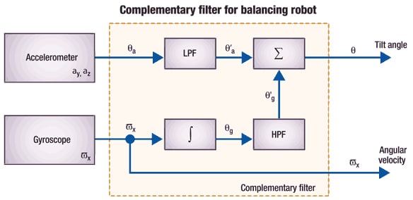
// Calculate gyro angle without any filter
gyroXangle += gyroXrate * dt
gyroYangle += gyroYrate * dt

// Calculate the angle using a Complimentary filter
compAngleX = 0.97 * (compAngleX + gyroXrate * dt) + 0.03 * accXangle
compAngleY = 0.97 * (compAngleY + gyroYrate * dt) + 0.03 * accYangle

- Kalman Filter
Kalman.cpp
float Q_angle = 0.001f;
float Q_bias = 0.003f;
float R_measure = 0.03f;

float angle = 0.0f; // Reset the angle
float bias = 0.0f; // Reset bias

float P[2][2] = {0.0, 0.0, 0.0, 0.0};

float Kalman::getAngle(float newAngle, float newRate, float dt) {
    rate = newRate - bias;
    angle += dt * rate;

    // Update estimation error covariance - Project the error covariance ahead
    /* Step 2 */
    P[0][0] += dt * (dt*P[1][1] - P[0][1] - P[1][0] + Q_angle);
    P[0][1] -= dt * P[1][1];
    P[1][0] -= dt * P[1][1];
    P[1][1] += Q_bias * dt;

    // Discrete Kalman filter measurement update equations - Measurement Update ("Correct")
    // Calculate Kalman gain - Compute the Kalman gain
    /* Step 4 */
    float S = P[0][0] + R_measure; // Estimate error
    /* Step 5 */
    float K[2]; // Kalman gain - This is a 2x1 vector
    K[0] = P[0][0] / S;
    K[1] = P[1][0] / S;

    // Calculate angle and bias - Update estimate with measurement zk (newAngle)
    /* Step 3 */
    float y = newAngle - angle; // Angle difference
    /* Step 6 */
    angle += K[0] * y;
    bias += K[1] * y;

    // Calculate estimation error covariance - Update the error covariance
    /* Step 7 */
    float P00_temp = P[0][0];
    float P01_temp = P[0][1];

    P[0][0] -= K[0] * P00_temp;
    P[0][1] -= K[0] * P01_temp;
    P[1][0] -= K[1] * P00_temp;
    P[1][1] -= K[1] * P01_temp;

    return angle;
};
Arduino Library: MPU9250

Sketchbook>MPU9250_DMP_Teapot


- click MPU9250Teapot/MPU9250Teapot.pde

Sketchbook>MPU9250_BasicAHRS2
x-io Technologies publications
Sketchbook> Robot> Esp32Copter


Ardupilot
Mission Planner Ground Control Station
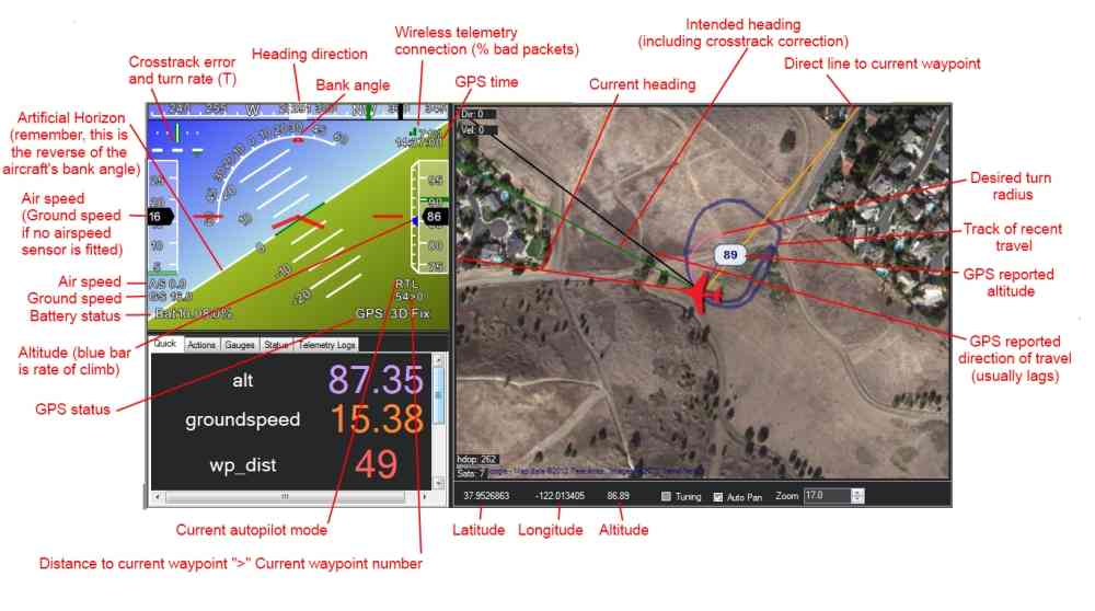
view of HUD
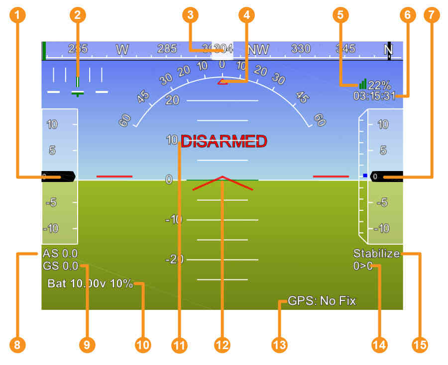
- Air speed ( Ground speed if no airspeed sensor is fitted )
- Crosstrack error and turn rate (T)
- Heading direction
- Bank angle
- Telemetry connection link quality (averaged percentage of good packets)
- GPS time
- Altitude ( blue bar is rate of climb )
- Air speed
- Ground speed
- Battery status
- Artificial Horizon
- Aircraft Attitude
- GPS Status
- Distance to Waypoint > Current Waypoint Number
- Current Flight Mode
This site was last updated June 17, 2025.