ESP32 PWM
Introduction to PWM functions
PWM (Pulse Width Modulation)
PWM Signal Properties
A typical PWM signal has the following properties that we can control by programming the microcontroller’s PWM peripheral’s registers. Such as PWM Frequency, PWM Resolution, and PWM Duty Cycle.
PWM architecture
 CMRx+1 >= CNR: PWM output high
CMRx+1 < CNR: PWM output low
PWM Frequency = PWM_Clock/(prescale+1)*(clock divider)/(CNR+1)
Duty ratio = (CMR+1)/(CNR+1)
NodeMCU-32S pinout

ESP32 PWM Channels
The ESP32 PWM controller has 8 high-speed channels and 8 low-speed channels, which gives us a total of 16 channels.
For each group, there are 4 timers / 8 channels. This means every two channels share the same timer. Therefore, we can’t independently control the PWM frequency of each couple of channels.

On NodeMCU-32S, GPIO34, GPIO35, GPIO36, GPIO39 don’t support PWM functionality, because they are input-only ADC pins.
ESP32 ledc APIs
List of all the LEDC APIs exposed by the driver. These functions are written for Arduino IDE port of ESP32.
ledcSetup(channel, frequency, resolution_bits);ledcAttachPin(pin, channel);ledcWrite(channel, dutycycle);ledcRead(channel);ledcWriteTone(channel, frequency);ledcWriteNote(channel, note, octave);ledcReadFreq(channel);ledcDetachPin(pin);
Some important points to remember while configuring PWM Channel in ESP32:
- As there are 16 PWM channels, the ‘channel’ argument takes any value between 0 and 15.
- Next is the frequency of the PWM signal. You can set the frequency as per your requirements like 1 KHz, 5 KHz, 8 KHz, and 10 KHz.
- The resolution of the PWM is also configurable and ESP32 PWM can be programmed anywhere between 1 bit to 16 bit resolution.
- PWM frequency and resolution are inversely proportional and is dependent on the clock source. So, be careful when selecting the values for frequency and resolution.
- Finally, assign a GPIO pin for PWM Output. You can assign any GPIO Pin but be careful when assigning (do not use already used GPIO pins like UART, SPI, etc.).
The following table shows a few commonly used PWM frequencies and resolutions.

[Homework]: ESP32_PWM_LED.ino

- Edit the following code, and Verify it on NodeMCU-32S with a LED
#define LED_GPIO   13
#define PWM1_Ch    0
#define PWM1_Res   8
#define PWM1_Freq  1000

int PWM1_DutyCycle = 0;

void setup()
{
  ledcAttachPin(LED_GPIO, PWM1_Ch);
  ledcSetup(PWM1_Ch, PWM1_Freq, PWM1_Res);
}

void loop()
{
  while(PWM1_DutyCycle < 255)
  {
    ledcWrite(PWM1_Ch, PWM1_DutyCycle++);
    delay(10);
  }
  while(PWM1_DutyCycle > 0)
  {
    ledcWrite(PWM1_Ch, PWM1_DutyCycle--);
    delay(10);
  }
}
DC Servo
Manage Libraries: ESP32Servo

- analogWrite.h
- analogWrite.cpp
- ESP32PWM.h
- ESP32PWM.cpp
- ESP32Servo.h
- ESP32Servo.cpp
- ESP32Tone.h
- ESP32Tone.cpp
Examples: ESP32Servo/PWMExample

Examples: ESP32Servo/Sweep


Examples: ESP32Servo/ToneExample


[Homework]: ESP32_SG90.ino
- read IO0 button to control SG90 rotation
- every press on IO0 button increase 30 degree, back to 0 degree after reaching 180 degree
PCA9685


DC Motor Driver
H-Bridge Motor Driver Circuit

Motor Control Pulse Width Modulator (MCPWM)
MCPWM Overview
 MCPWM Block Diagram


DRV8833 Dual H-Bridge Motor Driver

Manage Libraries: ESP32MotorControl
 ESP32MotorControl.h
ESP32MotorControl.cpp
// Attach one motor
void ESP32MotorControl::attachMotor(uint8_t gpioIn1, uint8_t gpioIn2)
{
    attachMotors(gpioIn1, gpioIn2, 0, 0);
}

// Attach two motors
void ESP32MotorControl::attachMotors(uint8_t gpioIn1, uint8_t gpioIn2, uint8_t gpioIn3, uint8_t gpioIn4)
{
    // debug
    debug("init MCPWM Motor 0");

    // Attach motor 0 input pins.
    // Set MCPWM unit 0
    mcpwm_gpio_init(MCPWM_UNIT_0, MCPWM0A, gpioIn1);
    mcpwm_gpio_init(MCPWM_UNIT_0, MCPWM0B, gpioIn2);

    // Indicate the motor 0 is attached.
    this->mMotorAttached[0] = true;

    // Attach motor 1 input pins.
    if (!(gpioIn3 == 0 && gpioIn4 ==0)) {
        debug("init MCPWM Motor 1");
        // Set MCPWM unit 1
        mcpwm_gpio_init(MCPWM_UNIT_1, MCPWM1A, gpioIn3);
        mcpwm_gpio_init(MCPWM_UNIT_1, MCPWM1B, gpioIn4);

        // Indicate the motor 1 is attached.
        this->mMotorAttached[1] = true;
    }

    // Initial MCPWM configuration

    debug ("Configuring Initial Parameters of MCPWM...");

    mcpwm_config_t pwm_config;
    pwm_config.frequency = 1000;    //frequency,
    pwm_config.cmpr_a = 0;              //duty cycle of PWMxA = 0
    pwm_config.cmpr_b = 0;              //duty cycle of PWMxb = 0
    pwm_config.counter_mode = MCPWM_UP_COUNTER;
    pwm_config.duty_mode = MCPWM_DUTY_MODE_0;

    mcpwm_init(MCPWM_UNIT_0, MCPWM_TIMER_0, &pwm_config);    //Configure PWM0A & PWM0B with above settings

    mcpwm_init(MCPWM_UNIT_1, MCPWM_TIMER_1, &pwm_config);    //Configure PWM1A & PWM1B with above settings

    debug ("MCPWM initialized");
}

// Motor set speed forward

void ESP32MotorControl::motorForward(uint8_t motor, uint8_t speed)
{
    if (!isMotorValid(motor)) {
        return;
    }

    if (speed == 100) { // Full speed
        motorFullForward(motor);
    } else {
        // Set speed -> PWM duty 0-100
        if (motor == 0) {
            mcpwm_set_signal_low(MCPWM_UNIT_0, MCPWM_TIMER_0, MCPWM_OPR_B);
            mcpwm_set_duty(MCPWM_UNIT_0, MCPWM_TIMER_0, MCPWM_OPR_A, speed);
            mcpwm_set_duty_type(MCPWM_UNIT_0, MCPWM_TIMER_0, MCPWM_OPR_A, MCPWM_DUTY_MODE_0); //call this each time, if operator was previously in low/high state

        } else {
            mcpwm_set_signal_low(MCPWM_UNIT_1, MCPWM_TIMER_1, MCPWM_OPR_B);
            mcpwm_set_duty(MCPWM_UNIT_1, MCPWM_TIMER_1, MCPWM_OPR_A, speed);
            mcpwm_set_duty_type(MCPWM_UNIT_1, MCPWM_TIMER_1, MCPWM_OPR_A, MCPWM_DUTY_MODE_0); //call this each time, if operator was previously in low/high state
        }
        mMotorSpeed[motor] = speed; // Save it
        mMotorForward[motor] = true;
        debug("Motor %u forward speed %u", motor, speed);
    }
}
Sketchbook>ESP32_RoboCar_DRV8833>

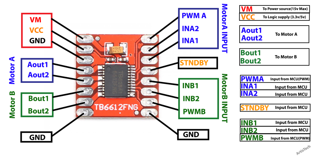
TB6612FNG Dual H-Bridge Motor Driver
The TB6612FNG is a dual motor driver IC from Toshiba.
- Power supply voltage: VM = 15 V(max)
- Output current; IOUT=1.2 A(ave) / 3.2 A (peak)
- Output low ON resistor; 0.5Ω (upper+lower Typ. @VM≥ 5 V)
- Standby (Power save) system
- PWM freq. : 100KHz (max)
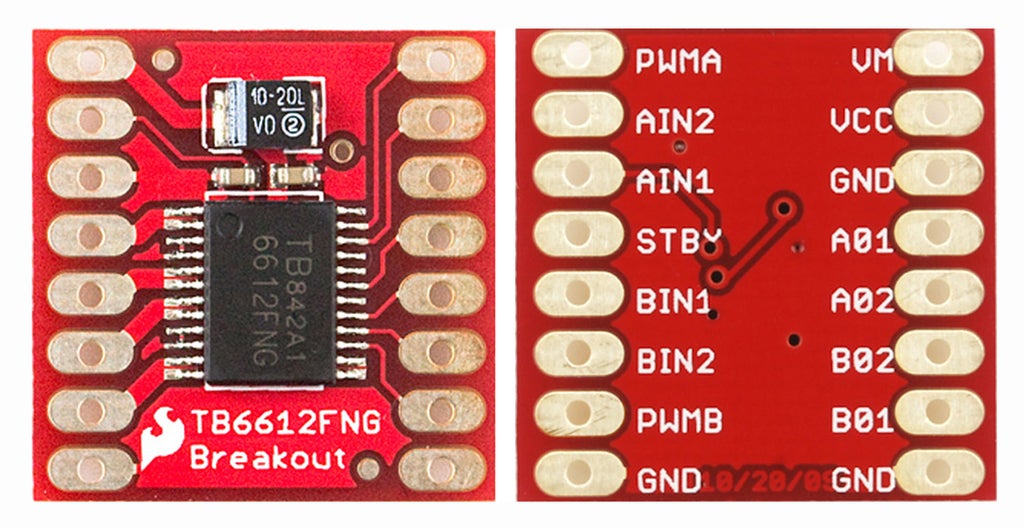
TB6612 driver
ESP32_TB6612.h
ESP32_TB6612.cpp
Motor::Motor(int In1pin, int In2pin, int PWMpin, int PWMch, int offset, int STBYpin)
{
  In1 = In1pin;
  In2 = In2pin;
  PWM = PWMpin;
  channel = PWMch;
  Standby = STBYpin;
  Offset = offset;

  pinMode(In1, OUTPUT);
  pinMode(In2, OUTPUT);
  pinMode(Standby, OUTPUT);
  ledcSetup(channel, DEFAULTFREQ, 10);
  ledcAttachPin(PWM, channel);
}

void Motor::fwd(int speed, int ch)
{
   digitalWrite(In1, HIGH);
   digitalWrite(In2, LOW);
   ledcWrite(ch, speed);
}

void Motor::rev(int speed, int ch)
{
   digitalWrite(In1, LOW);
   digitalWrite(In2, HIGH);
   ledcWrite(ch, speed);
}

void Motor::brake()
{
   digitalWrite(In1, LOW);
   digitalWrite(In2, LOW);
}

void Motor::standby()
{
   digitalWrite(Standby, LOW);
}
Sketchbook>ESP32_RoboCar_TB6612_MPU6050_SR04_BLE

3D Printer
主機板套件

A4988
A4988 is a complete microstepping motor driver with built-in translator for easy operation.


How To Control a Stepper Motor with A4988 Driver and Arduino

/*     Simple Stepper Motor Control Example Code
 *
 *  by Dejan Nedelkovski, www.HowToMechatronics.com
 *
 */

// defines pins numbers
const int stepPin = 3;
const int dirPin = 4;

void setup() {
  // Sets the two pins as Outputs
  pinMode(stepPin,OUTPUT);
  pinMode(dirPin,OUTPUT);
}

void loop() {
  digitalWrite(dirPin,HIGH); // Enables the motor to move in a particular direction
  // Makes 200 pulses for making one full cycle rotation
  for(int x = 0; x < 200; x++) {
    digitalWrite(stepPin,HIGH);
    delayMicroseconds(500);
    digitalWrite(stepPin,LOW);
    delayMicroseconds(500);
  }
  delay(1000); // One second delay

  digitalWrite(dirPin,LOW); //Changes the rotations direction
  // Makes 400 pulses for making two full cycle rotation
  for(int x = 0; x < 400; x++) {
    digitalWrite(stepPin,HIGH);
    delayMicroseconds(500);
    digitalWrite(stepPin,LOW);
    delayMicroseconds(500);
  }
  delay(1000);
}
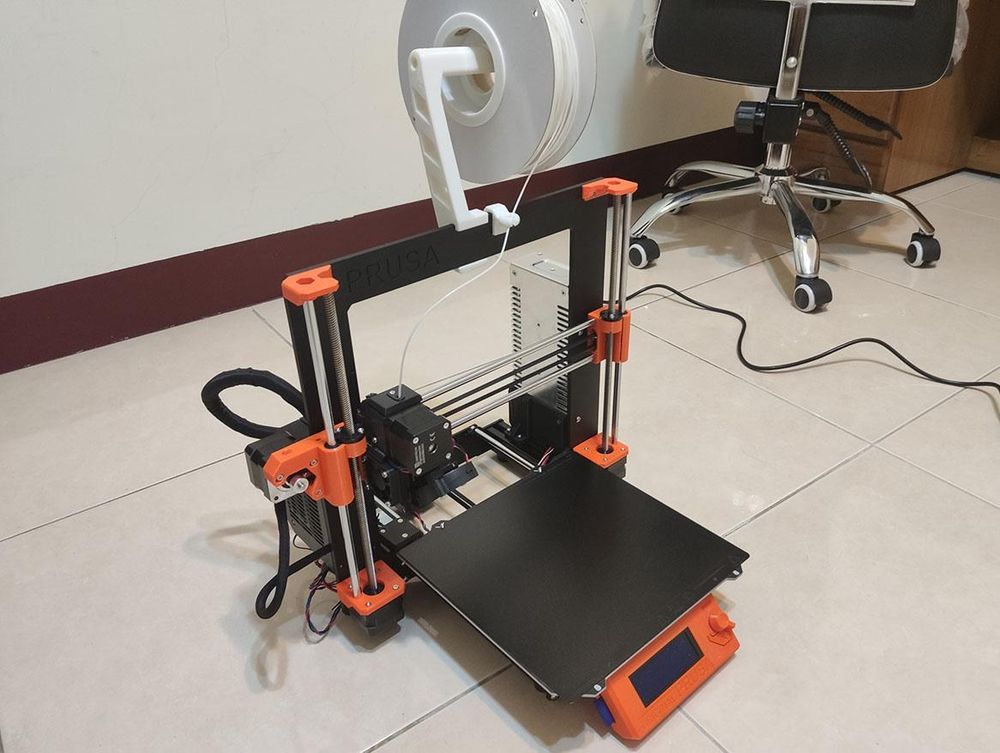
Prusa i3 MK3S 組裝
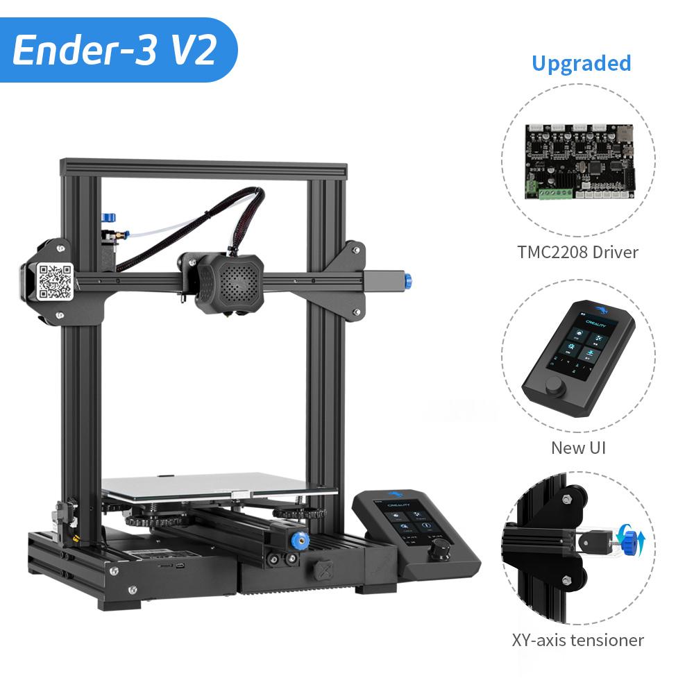
Creality3D Ender-3 V2
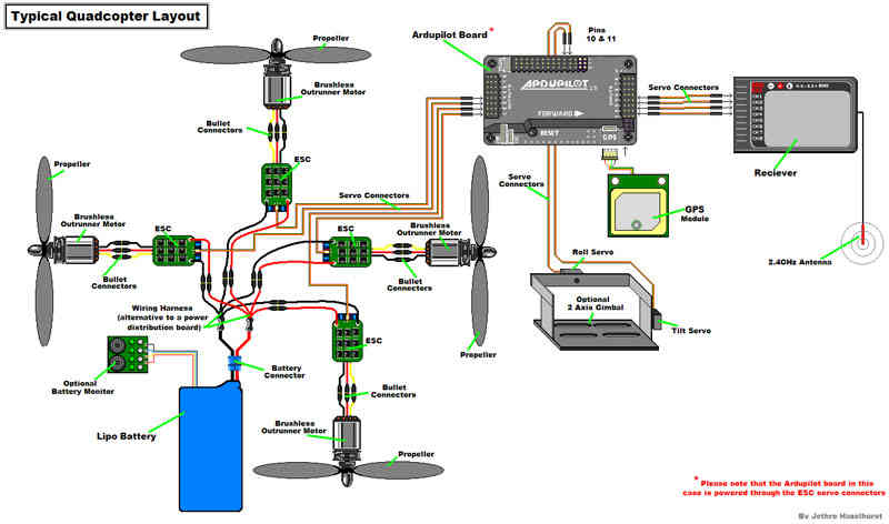
Drone
新手DIY多軸飛行器——我的第一架450無人機
 QAV250穿越機套件

F450空拍機套件
 |
 |
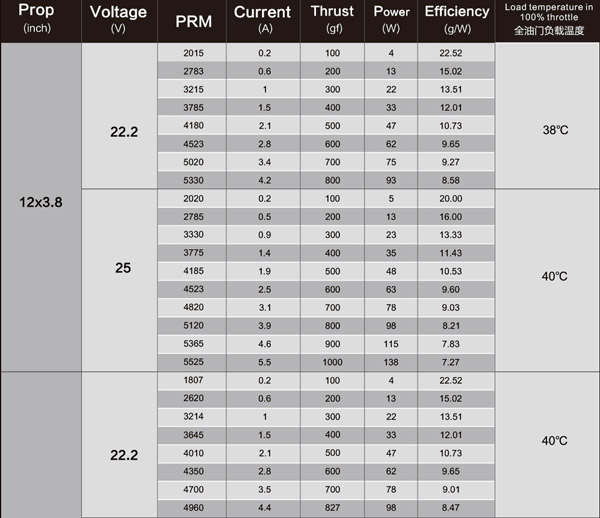
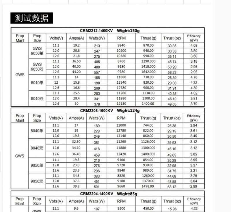
無人機電機
電機的種類及區別
對於多旋翼無人機來說,小型無人機通常使用有刷電機,比如空心杯電機;而軸距較大,通常大於200mm左右的無人機都使用無刷電機。
目前的無人機多以無刷電機 中的永磁同步電機爲主。
無刷電機:可連續工作20000小時 左右,常規的使用壽命7-10年。
有刷電機:可連續工作5000小時左右,常規的使用壽命2-3年。
電機的基本參數
最大電流(A),最大電壓(V),KV值。
KV值:指電機在單位電壓下的轉速。一般KV值越高,代表電機的轉速越快。
比方說:KV值爲1000,意思是:此電機在1V電壓下,每分鐘轉速爲1000轉。
電機的命名
四位數字,前兩位是定子的直徑,後兩位是定子的高度。如4108規格的電機,定子的直徑是41mm,高度是8mm。
如何選配電機
多旋翼的電機最大拉力總和不應低於總重的1.5倍,最好是兩倍朝上。
2212 950KV for 四軸F450/F350

4004 KV300 for 四足機器人

共軸雙槳

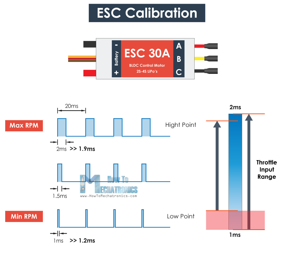
ESC (Electronic Speed Controller) 電調
Arduino Brushless Motor Control Tutorial | ESC | BLDC
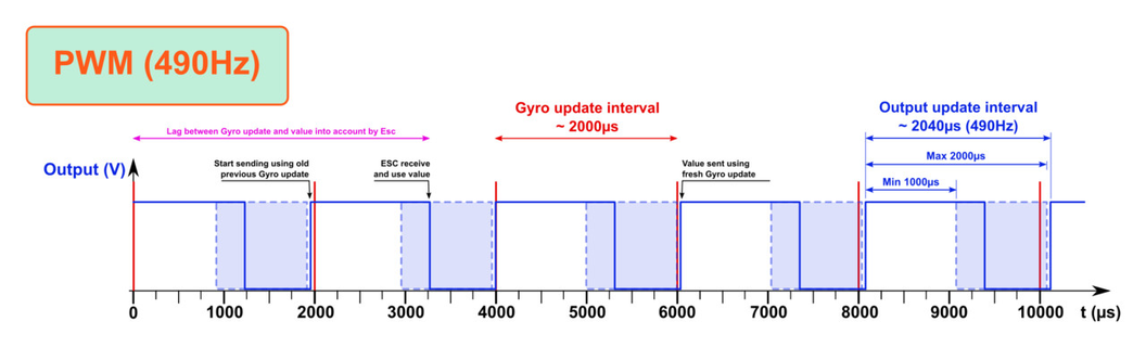
PWM Signal = 50Hz (20ms)
RPM Min ~ Mid ~ Max = 1ms ~ 1.5ms ~ 2ms
Examples of ESC control
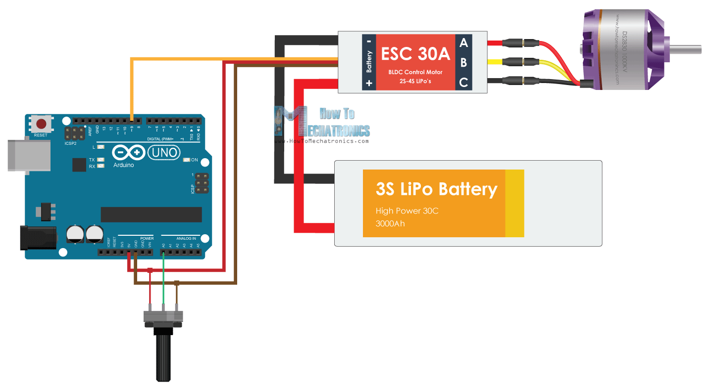
// Brushless Motor Control
#include <Servo.h>

Servo ESC;

int potValue;  // value from the analog pin
https://github.com/rkuo2000/MCU-course/tree/main/images
void setup() {
  // Attach the ESC on pin 9
  ESC.attach(9,1000,2000); // (pin, min pulse width, max pulse width in microseconds)
}

void loop() {
  potValue = analogRead(A0);   // reads the value of the potentiometer (value between 0 and 1023)
  potValue = map(potValue, 0, 1023, 0, 180);   // scale it to use it with the servo library (value between 0 and 180)
  ESC.write(potValue);    // Send the signal to the ESC
}
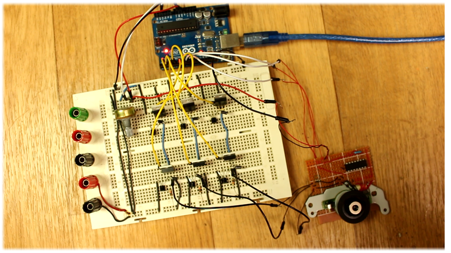
Sensored ESC -Homemade
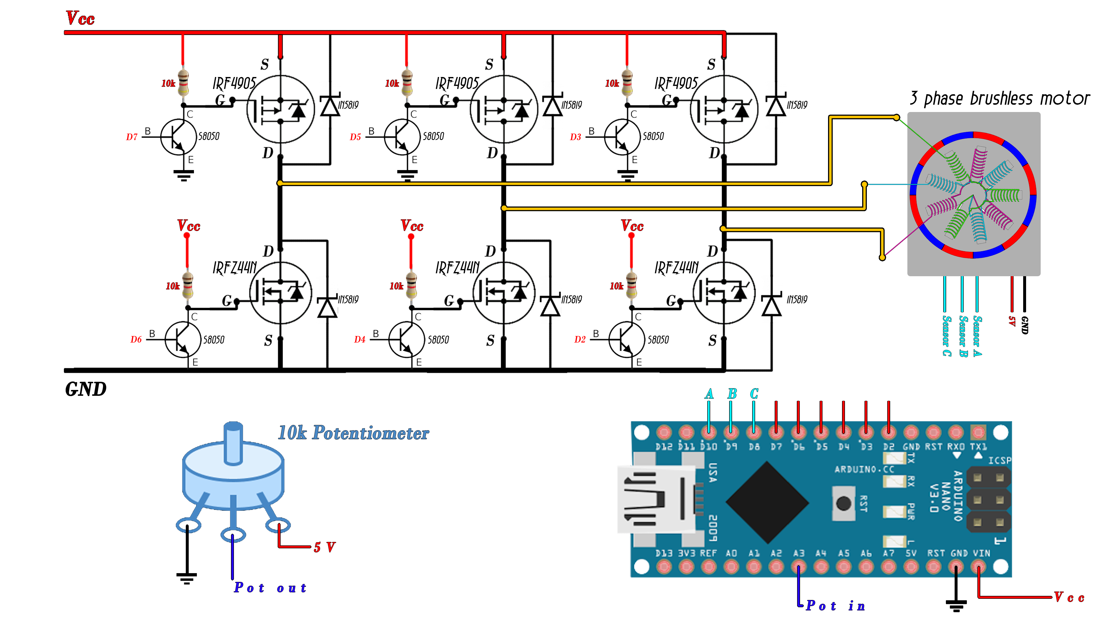
/*
 * Electronoobs sensored brushed motor electronic speed controller code
 * Connect the sensors to pins 8, 9 and 10
 * High gates to pins 7, 5 and 3
 * Low gates to 6, 4 and 2
 * More on http://www.electronoobs.com/eng_circuitos_tut19.php
 */

int pot = A3;
int SensorA = 8;
int SensorB = 9;
int SensorC = 10;


int fase = 1;
int Delay=4000;
unsigned long previousMillis = 0;
unsigned long currentMillis = 0;

void setup() {
  pinMode(pot,INPUT);
  pinMode(SensorA,INPUT);
  pinMode(SensorB,INPUT);
  pinMode(SensorC,INPUT);

  DDRD  |= B11111100;  // Sets D2, D3, D4, D5, D6 and D7 as OUTPUT
  PORTD &= B00000011;  // D2-D7 LOW
  PCICR |= (1 << PCIE0);    //enable PCMSK0 scan
  PCMSK0 |= (1 << PCINT0);  //Set pin D8 trigger an interrupt on state change.   A
  PCMSK0 |= (1 << PCINT1);  //Set pin D9 trigger an interrupt on state change.   B
  PCMSK0 |= (1 < PCINT2);  //Set pin D10 trigger an interrupt on state change.      C

  currentMillis = micros();
}


void loop() {
  currentMillis = micros();
  if(currentMillis - previousMillis >= Delay){

    previousMillis += Delay;

    switch(fase){

      //Phase1 A-B
      	case 1:
        PORTD = B10010000;  //  Pin 7 and 4 to HIGH
        break;

        //Phase2 C-B
        case 2:
        PORTD = B00011000;  //  Pin 3 and 4 to HIGH
        break;

        //Phase3 C-A
        case 3:
        PORTD = B01001000;  //  Pin 3 and 6 to HIGH
        break;

        //Phase4 B-A
        case 4:
        PORTD = B01100000;  //  Pin 5 and 6 to HIGH
        break;

        //Phase5 B-C
        case 5:
        PORTD = B00100100;  //  Pin 5 and 2 to HIGH
        break;

        //Phase6 A-C
        case 6:
        PORTD = B10000100;  //  Pin 7 and 2 to HIGH
        break;
    }//end of switch
  }//Case of if millis

  Delay=map(analogRead(pot),0,1024,1,4000); //we obtain the delay speed using the potentiometer
}//Void end

ISR(PCINT0_vect){
  if(  (PINB & B00000101) && fase == 6  ){
    fase = 1;
  }

  if(  (PINB & B00000100) && fase == 1 ){
    fase = 2;
  }

  if(  (PINB & B00000110) && fase == 2 ){
    fase = 3;
  }

  if(  (PINB & B00000010) && fase == 3 ){
    fase = 4;
  }

  if(  (PINB & B00000011) && fase == 4 ){
    fase = 5;
  }

  if(  (PINB & B00000001) && fase == 5 ){
    fase = 6;
  }
}
This site was last updated June 17, 2025.