ESP32 GPIO
Introduction to GPIO pin functions (debounce, pullup, interrupt), OneWire interface with DS18B20, DHT11, and IR Remote.
MCU - Micro Control Unit (Microcontroller)
A MCU consist of a processor core, memory and I/O interfaces
NodeMCU-32S pinout

GPIO (General Purpose I/O)

Each IO pad drive/sink ~25mA, Entire Chip drive/sink ~200mA

Arduino Digital IO
GPIO write
-
defines:
#define ledPin 2 -
setup():
pinMode(ledPin, OUTPUT);
GPIO read
-
defines:
#define sensorPin 23 -
setup():
pinMode(sensorPin, INPUT); -
loop():
sensor_state = digitalread(sensorPin);
Examples/01.Basics/Blink
-
NodeMCU-32S has a built-in LED on GPIO2.
#define LED_BUILTIN 2 - setup() : To setup MCU’s default value, setup() is run only once after power-up or reset
void setup() { // initialize digital pin LED_BUILTIN as an output. pinMode(LED_BUILTIN, OUTPUT); } - loop(): The main is loop() that keeps running forever.
// the loop function runs over and over again forever
void loop() {
digitalWrite(LED_BUILTIN, HIGH);   // turn the LED on (HIGH is the voltage level)
delay(1000);                       // wait for a second
digitalWrite(LED_BUILTIN, LOW);    // turn the LED off by making the voltage LOW
delay(1000);                       // wait for a second
}
Sensors
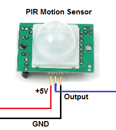
Passive InfraRed sensor: PIR (人體紅外線感應)
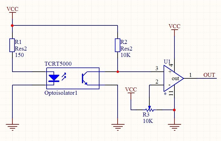
Reflective InfraRed sensor: TCRT5000 (反射式光電開關)

 |
 |
[Homework] GPIO_read.ino
- Using ArduinoIDE to edit the code, and save as GPIO_read.ino
- Verify the code on NodeMCU-32S with a push button to Ground.
- Then upload GPIO_read.ino to https://www.github.com/yourname/arduino
#define inputPin 23

void setup() {
  Serial.begin(9600);
  pinMode(inputPin, INPUT);
}

void loop() {
  IOstate = digitalread(inputPin);
  Serial.println(IOstate);
  delay(200); // delay 200ms for next GPIO read
}
Examples/01.Basics/DigitalReadSerial
- Onboard Button BOOT/IO is connected to GPIO0
- Modify to pushButton =2, so we can read BOOT button status.
int pushButton = 0;
// the setup routine runs once when you press reset:
void setup() {
  // initialize serial communication at 9600 bits per second:
  Serial.begin(9600);
  // make the pushbutton's pin an input:
  pinMode(pushButton, INPUT);
}

// the loop routine runs over and over again forever:
void loop() {
  // read the input pin:
  int buttonState = digitalRead(pushButton);
  // print out the state of the button:
  Serial.println(buttonState);
  delay(1);        // delay in between reads for stability
}
- Open the monitor & set 9600 baud to see serial print-out from running program in Arduino IDE.

- Press BOOT(IO0) button will see readout changed to 0, release BOOT button will see readout =1
- If change to Serial.begin(115200), then change monitor to 115200 baud to match the serial baudrate.
Examples/02.Digital/Button
- Ths example is to read the buttonPin state, then output to the state (High/Low) to ledPin
- Modify pin IOs (buttonpin =0; ledPin =2)
const int buttonPin = 0;(using BOOT/IO0 button)
const int ledPin =2;(output to built-in LED)
// constants won't change. They're used here to set pin numbers:
const int buttonPin = 2;     // the number of the pushbutton pin
const int ledPin =  13;      // the number of the LED pin

// variables will change:
int buttonState = 0;         // variable for reading the pushbutton status

void setup() {
  // initialize the LED pin as an output:
  pinMode(ledPin, OUTPUT);
  // initialize the pushbutton pin as an input:
  pinMode(buttonPin, INPUT);
}

void loop() {
  // read the state of the pushbutton value:
  buttonState = digitalRead(buttonPin);

  // check if the pushbutton is pressed. If it is, the buttonState is HIGH:
  if (buttonState == HIGH) {
    // turn LED on:
    digitalWrite(ledPin, HIGH);
  } else {
    // turn LED off:
    digitalWrite(ledPin, LOW);
  }
}
Examples/02.Digital/Debounce
- This example is to add debounce-delay before reading the buttonPin.
- Modify pin IOs (buttonpin =0; ledPin =2)
unsigned long debounceDelay = 50;(50ms duration for reading GPIO0 button)
// constants won't change. They're used here to set pin numbers:
const int buttonPin = 0;    // the number of the pushbutton pin
const int ledPin = 2;      // the number of the LED pin

// Variables will change:
int ledState = HIGH;         // the current state of the output pin
int buttonState;             // the current reading from the input pin
int lastButtonState = LOW;   // the previous reading from the input pin

// the following variables are unsigned longs because the time, measured in
// milliseconds, will quickly become a bigger number than can be stored in an int.
unsigned long lastDebounceTime = 0;  // the last time the output pin was toggled
unsigned long debounceDelay = 50;    // the debounce time; increase if the output flickers

void setup() {
  pinMode(buttonPin, INPUT);
  pinMode(ledPin, OUTPUT);

  // set initial LED state
  digitalWrite(ledPin, ledState);
}

void loop() {
  // read the state of the switch into a local variable:
  int reading = digitalRead(buttonPin);

  // check to see if you just pressed the button
  // (i.e. the input went from LOW to HIGH), and you've waited long enough
  // since the last press to ignore any noise:

  // If the switch changed, due to noise or pressing:
  if (reading != lastButtonState) {
    // reset the debouncing timer
    lastDebounceTime = millis();
  }

  if ((millis() - lastDebounceTime) > debounceDelay) {
    // whatever the reading is at, it's been there for longer than the debounce
    // delay, so take it as the actual current state:

    // if the button state has changed:
    if (reading != buttonState) {
      buttonState = reading;

      // only toggle the LED if the new button state is HIGH
      if (buttonState == HIGH) {
        ledState = !ledState;
      }
    }
  }

  // set the LED:
  digitalWrite(ledPin, ledState);

  // save the reading. Next time through the loop, it'll be the lastButtonState:
  lastButtonState = reading;
}
Examples/02.Digital/DigitalInputPullup
- Configure pin 0 as an input and enable the internal pull-up resistor
pinMode(0, INPUT_PULLUP);
pinMode(2, OUTPUT);
void setup() {
  //start serial connection
  Serial.begin(9600);
  //configure pin 2 as an input and enable the internal pull-up resistor
  pinMode(0, INPUT_PULLUP);
  pinMode(2, OUTPUT);

}

void loop() {
  //read the pushbutton value into a variable
  int sensorVal = digitalRead(2);
  //print out the value of the pushbutton
  Serial.println(sensorVal);

  // Keep in mind the pull-up means the pushbutton's logic is inverted. It goes
  // HIGH when it's open, and LOW when it's pressed. Turn on pin 13 when the
  // button's pressed, and off when it's not:
  if (sensorVal == HIGH) {
    digitalWrite(2, LOW);
  } else {
    digitalWrite(2, HIGH);
  }
}
GPIO Interrupt
The ESP32 offers up to 32 interrupt slots for each core. Each interrupt has a certain priority level and can be categorized into two types.
- Hardware Interrupts – These occur in response to an external event. For example, GPIO Interrupt(when a key is pressed down) or a Touch Interrupt(when touch is detected)
- Software Interrupts – These occur in response to a software instruction. For example, a Simple Timer Interrupt or Watchdog Timer Interrupt(when timer times out)
attachInterrupt()
-
Using Interrupts
Interrupts are useful for making things happen automatically in microcontroller programs and can help solve timing problems. Good tasks for using an interrupt may include reading a rotary encoder, or monitoring user input. -
Interrupt Service Routines(ISR)
ISRs are special kinds of functions that have some unique limitations most other functions do not have. An ISR cannot have any parameters, and they shouldn’t return anything.
Attach interrup to a GPIO pin
attachInterrupt(digitalPinToInterrupt(pin), ISR, mode)
- GPIOPin – sets the GPIO pin as an interrupt pin, which tells the ESP32 which pin to monitor. -
- ISR – is the name of the function that will be called every time the interrupt is triggered.
- Mode – defines when the interrupt should be triggered. Five constants are predefined as valid values:
- LOW to trigger the interrupt whenever the pin is low,
- CHANGE to trigger the interrupt whenever the pin changes value
- RISING to trigger when the pin goes from low to high,
- FALLING for when the pin goes from high to low.
Detaching Interrupt from a GPIO Pin
detachInterrupt(GPIOPin);
Interrupt Service Routine
void IRAM_ATTR ISR() {
    Statements;
}
[Homework] GPIO_Interrupt.ino
- save the program code to ~/Documents/Arduino/examples/attachInterrupt as file “GPIO_Interrupt.ino”
- verify the code on NodeMCU-32S board
- then upload GPIO_Interrupt.ino to https://www.github.com/yourname/arduino
const byte ledPin = 2;       // Builtin-LED pin
const byte interruptPin = 0; // BOOT/IO0 button pin
volatile byte state = LOW;

void setup() {
  pinMode(ledPin, OUTPUT);
  pinMode(interruptPin, INPUT_PULLUP);
  attachInterrupt(digitalPinToInterrupt(interruptPin), blink, FALLING);
}

void loop() {
  digitalWrite(ledPin, state);
}

void blink() {
  state = !state;
}
HC-SR04
Using the HC-SR04 Ultrasonic Distance Sensor with Arduino


- Waterproof-type is the same as Car Parking Radar (倒車雷達)

- Trigger : 10us pulse
digitalWrite(trigPin, LOW); delayMicroseconds(2); digitalWrite(trigPin, HIGH); delayMicroseconds(10); digitalWrite(trigPin, LOW); - Echo : HIGH width = ultrasound travel time
// Measure the response from the HC-SR04 Echo Pin
duration = pulseIn(echoPin, HIGH);

// Determine distance from duration
// Use 343 metres per second as speed of sound

distance = (duration / 2) * 0.0343;
 |
 |
Install HCSR04 Library
 Afstandssensor-HCSR04: ~/Documents/Arudino/libraries/Afstandssenor_-_HCSR04
afstandssensor.h
afstandssensor.cpp
double AfstandsSensor::afstandCM(float temperature) {
    // Sikre først at triggerPin er LAV
    digitalWrite(triggerPin, LOW);
    delayMicroseconds(2);
    //For at aktivere sensoren holdes triggerPin HØJ i 10 microsekunder.
    digitalWrite(triggerPin, HIGH);
    delayMicroseconds(10);
    digitalWrite(triggerPin, LOW);
    //Sensoren retunere nu afstanden med at holde echoPin HØJ i en periode svarende til afstanden målt.
    unsigned long durationMicroSec = pulseIn(echoPin, HIGH);

    double speedOfSoundInCmPerMs = 0.03313 + 0.0000606 * temperature; // Cair ≈ (331.3 + 0.606 ⋅ ϑ) m/s
    double distanceCm = durationMicroSec / 2.0 * speedOfSoundInCmPerMs;
    if (distanceCm == 0 || distanceCm > 400) {
        return -1.0 ;
    } else {
        return distanceCm;
    }
}
Examples>Afstandssensor-HCSR04>afstand
- NodeMCU-32S connections to HC-SR04 (+5V, Trig, Echo, Gnd)
 |
 |
-
Modify trigPin = 23, echoPin = 22 & reduce delay to 40ms

-
Tools>Serial Monitor>

1-Wire Interface
Guide to 1-Wire Communication
The basis of 1-Wire® technology is a serial protocol using a single data line plus ground reference for communication. A 1-Wire master initiates and controls the communication with one or more 1-Wire slave devices on the 1-Wire bus (Figure below). Each 1-Wire slave device has a unique, unalterable, factory-programmed, 64-bit identification number (ID), which serves as device address on the 1-Wire bus. The 8-bit family code, a subset of the 64-bit ID, identifies the device type and functionality. Typically, 1-Wire slave devices operate over the following four voltage ranges:
- 1.71V (min) to 1.89V (max)
- 1.71V (min) to 3.63V (max)
- 2.97V (min) to 3.63V (max)
- 2.8V (min) to 5.25V (max)

The DS2432 is a 1024 bits of EEPROM with 1-Wire interface

DS18B20
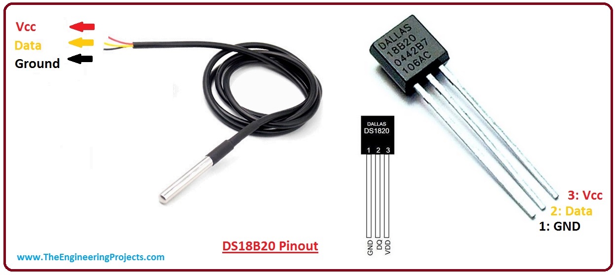
DS1820 Datasheet
Features:
- Unique 1-Wire interface requires only one port pin for communication
- Multidrop capability simplifies distributedtemperature sensing applications
- Requires no external components
- Can be powered from data line. Power supplyrange is 3.0V to 5.5V
- Zero standby power required
- Measures temperatures from -55°C to+125°C. Fahrenheit equivalent is -67°F to+257°F
- ±0.5°C accuracy from -10°C to +85°C
- Thermometer resolution is programmablefrom 9 to 12 bits
- Converts 12-bit temperature to digital word in750 ms (max.)
Install DS18B20 library
Tools>Managing Libraries> select DS18B20 & Install All

OneWire library: ~/Documents/Arduino/libraries/OneWire
OneWire.h
OneWire.cpp
DS18B20 Initial Timing (Reset)

// Perform the onewire reset function.  We will wait up to 250uS for
// the bus to come high, if it doesn't then it is broken or shorted
// and we return a 0;
//
// Returns 1 if a device asserted a presence pulse, 0 otherwise.
//
uint8_t OneWire::reset(void)
{
        IO_REG_TYPE mask IO_REG_MASK_ATTR = bitmask;
        volatile IO_REG_TYPE *reg IO_REG_BASE_ATTR = baseReg;
        uint8_t r;
        uint8_t retries = 125;

        noInterrupts();
        DIRECT_MODE_INPUT(reg, mask);
        interrupts();
        // wait until the wire is high... just in case
        do {
                if (--retries == 0) return 0;
                delayMicroseconds(2);
        } while ( !DIRECT_READ(reg, mask));

        noInterrupts();
        DIRECT_WRITE_LOW(reg, mask);
        DIRECT_MODE_OUTPUT(reg, mask);  // drive output low
        interrupts();
        delayMicroseconds(480);
        noInterrupts();
        DIRECT_MODE_INPUT(reg, mask);   // allow it to float
        delayMicroseconds(70);
        r = !DIRECT_READ(reg, mask);
        interrupts();
        delayMicroseconds(410);
        return r;
}
Read Write Timing

void OneWire::write_bit(uint8_t v)
{
        IO_REG_TYPE mask IO_REG_MASK_ATTR = bitmask;
        volatile IO_REG_TYPE *reg IO_REG_BASE_ATTR = baseReg;

        if (v & 1) {
                noInterrupts();
                DIRECT_WRITE_LOW(reg, mask);
                DIRECT_MODE_OUTPUT(reg, mask);  // drive output low
                delayMicroseconds(10);
                DIRECT_WRITE_HIGH(reg, mask);   // drive output high
                interrupts();
                delayMicroseconds(55);
        } else {
                noInterrupts();
                DIRECT_WRITE_LOW(reg, mask);
                DIRECT_MODE_OUTPUT(reg, mask);  // drive output low
                delayMicroseconds(65);
                DIRECT_WRITE_HIGH(reg, mask);   // drive output high
                interrupts();
                delayMicroseconds(5);
        }
}
uint8_t OneWire::read_bit(void)
{
        IO_REG_TYPE mask IO_REG_MASK_ATTR = bitmask;
        volatile IO_REG_TYPE *reg IO_REG_BASE_ATTR = baseReg;
        uint8_t r;

        noInterrupts();
        DIRECT_MODE_OUTPUT(reg, mask);
        DIRECT_WRITE_LOW(reg, mask);
        delayMicroseconds(3);
        DIRECT_MODE_INPUT(reg, mask);   // let pin float, pull up will raise
        delayMicroseconds(10);
        r = DIRECT_READ(reg, mask);
        interrupts();
        delayMicroseconds(53);
        return r;
}
Examples>OneWire>DS18x20_Temperature
-
DS18B20 connected to ESP32 GPIO23, and a 10K resistor pull-up to +5V.

-
Modify DS18x20_Temperature.ino to use GPIO23

-
Open ArduinoIDE monitor to see DS18x20_Temperature running.

DHT11

DHT11 Datasheet
Typical Application

Overall Communication Process

DHT11 Response

DHT11 Data Transmission
 |
 |
Install DHT11 library
Tools>Managing Libraries> select DHT sensory library & Install All

DHT11 library: ~/Documents/Arduino/libraries/DHT_sensor_library
DHT.h
DHT.cpp
Examples/DHT11 sensor library/DHTtester

-
modify DHTPIN to GPIO23 & DHTTYPE to DHT11
#define DHTPIN 23
#define DHTTYPE DHT11

-
Open ArduinoIDE monitor to see DHT11 readout.

IR Remote
Infra-Red Light
Infra-Red light is actually normal light with a particular colour. We humans can’t see this colour because its wave length of about 950nm is below the visible spectrum.
Modulation
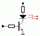
Modulation of the signal on a carrier frequency is the answer to make our signal stand out above the noise. With modulation we make the IR light source blink in a particular frequency.
- Transmitter
- Receiver
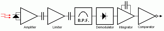
As you can see only the AC signal is sent to the Band Pass Filter. The Band Pass Filter is tuned to the carrier frequency of the handset unit. Common carrier frequencies range from 30kHz to 60kHz in consumer electronics, so it is important to pick the right one.
 Siemens has its SFH506-xx series, where xx denotes the carrier frequency of 30, 33, 36, 38, 40 or 56kHz.
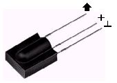
 VS1838B
- Working Voltage: 2.7V to 5.5V
- Reception Distance: 23M
- Reception Angle: ± 35 Degree
- Low Level Voltage: 0.4V
- High Level Voltage: 4.5V
- Material: Plastic, Alloy
- Color: Black, Silver Tone
- Carrier frequency: 38KHz

IR Protocol : NEC, SONY SIRC, PHILIPS RC5 & RC6, FUJITSU AC protocols.
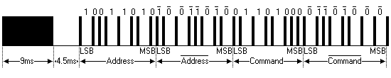
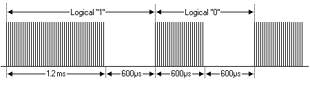
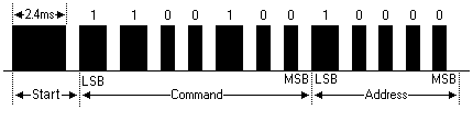
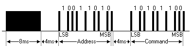
NEC protocol
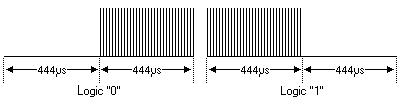
The NEC IR transmission protocol uses pulse distance encoding of the message bits. Each pulse burst (mark – RC transmitter ON) is 562.5µs in length, at a carrier frequency of 38kHz (26.3µs). Logical bits are transmitted as follows:
- 8 bit address and 8 bit command length.
- Carrier frequency of 38kHz.
- Bit time of 1.125ms or 2.25ms.

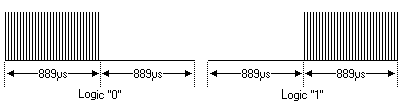
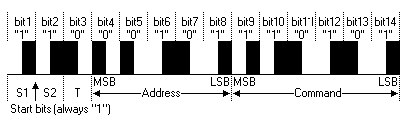
SONY SIRC protocol
SIRC is a proprietary protocol by SONY and there exist three variants, with 12, 15 or 20 bits. Command field is length-fixed with 7 bits in all the three versions. All the information bits are streamed LSB first.
Features:
- 12-bit version, 7 command bits, 5 address bits.
- 15-bit version, 7 command bits, 8 address bits.
- 20-bit version, 7 command bits, 5 address bits, 8 extended bits.
- Pulse width modulation.
- Carrier frequency of 40kHz.
- Bit time of 1.2ms or 0.6ms.
PHILIPS RC5 & RC6 protocol
RC5 and RC6 are two different protocols by Philips, both based on the Manchester coding. Their carrier frequency is set at 36KHz with a recommended PWM duty cycle of 1/4 or 1/3 but, again, it’s not mandatory.
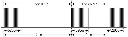
X-Sat / Mitsubishi Protocol
Features
- 8 bit address and 8 bit command length.
- Pulse distance modulation.
- Carrier frequency of 38kHz.
- Bit time of 1ms or 2ms.
FUJITSU AC protocol
The carrier frequency is set at 38KHz with a basic time interval T of approximately 420us, 16 cycles of the carrier frequency.
The start frame consists of 128us (8x T) followed by a pause of 64us (4x T ). Logical 1 consists of a pulse of length T followed by a pause of the same length, while a logical 0 has a pause of 2x T . Then there is a tail which is just a pulse of length T.
Some decoded values are:
SET:
0x28C6000808 36

SWING:
0x28C6000808 B6

TEMPERATURE: (27-26-25 °C)
0x28C6000808 3F 100C0D4 000000000 78
0x28C6000808 3F 100C054 000000000 74
0x28C6000808 3F 100C094 000000000 7C

MASTER (Here it is in 'Fan' mode):
0x28C6000808 3F 100C05C 000000000 B4
Install IRremote library
Tools>Managing Libraries> select IRremote & Install All

IRremote library: ~/Documents/Arduino/libraries/IRremote
IRremote Sender to IRremote Receiver

Examples> IRremote> SimpleSender

Examples> IRremote> SimpleReceiver

Examples> IRremote> SendAndReceive


- Open ArduinoIDE monitor & set baud to 115200
[Homework] IRremote_Button
Function: use BOOT button to trigger IRremote Sender to Receiver
Coding: IRremote_Button.ino = attachInterrupt.ino + SimpleSender.ino + SimpleReceiver.ino
- create IRremote_button.ino & save
- copy PinDefinitionsAndMore.h
- verify the code on NodeMCU-32S board
- then upload IRremote_Button.ino to https://www.github.com/yourname/arduino
Hint:
#include <Arduino.h>

/* Defines of GPIO_Interrupt.ino */
const byte ledPin = 2;       // Builtin-LED pin
const byte interruptPin = 0; // BOOT/IO0 button pin
volatile byte state = LOW;

/* Defines of SendAndReceive.ino */
// select only NEC and the universal decoder for pulse width or pulse distance protocols
#define DECODE_NEC          // Includes Apple and Onkyo
#define DECODE_DISTANCE     // in case NEC is not received correctly

#include "PinDefinitionsAndMore.h"
#define INFO // To see valuable informations from universal decoder for pulse width or pulse distance protocols

#include <IRremote.hpp>

#define DELAY_AFTER_SEND 2000
#define DELAY_AFTER_LOOP 5000

void setup() {
  Serial.begin(9600);
  pinMode(ledPin, OUTPUT);
  pinMode(interruptPin, INPUT_PULLUP);
  attachInterrupt(digitalPinToInterrupt(interruptPin), IRsender, FALLING);

  /* get code from setup() in SendAndReceive.ino */

}

void loop() {
  Serial.println("IR receiving...");
  /* get Receiver code from SendAndReceive.ino */
}

void IRsender() {
  Serial.println("IR sending...");
  /* get Sender code from SendAndReceiv.ino */
}
[Project: ESP8266 IRremote]
- ESP8266 pin D3 connected to IR-Led
- Sketch/ESP8266_Webserver_IRremote: upload code to ESP8266


Stepper Motor (步進馬達)
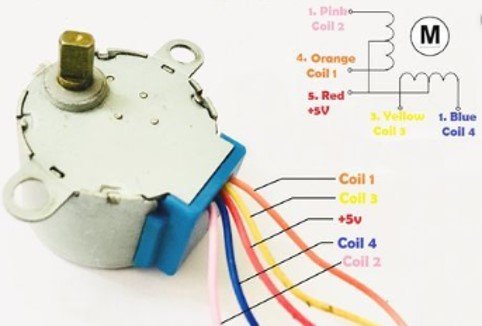
Operation principle of stepper motor
- Clockwise (CW) control(順時針控制)
- Counterclockwise (CCW) Control (逆時針控制)
Install Stepper Library

- Stepper.h
The sequence of control signals for 4 control wires is as follows:Step C0 C1 C2 C3 1 1 0 1 0 2 0 1 1 0 3 0 1 0 1 4 1 0 0 1 - Stepper.cpp
``` /* - Moves the motor forward or backwards. */ void Stepper::stepMotor(int thisStep) {
if (this->pin_count == 4) { switch (thisStep) { case 0: // 1010 digitalWrite(motor_pin_1, HIGH); digitalWrite(motor_pin_2, LOW); digitalWrite(motor_pin_3, HIGH); digitalWrite(motor_pin_4, LOW); break; case 1: // 0110 digitalWrite(motor_pin_1, LOW); digitalWrite(motor_pin_2, HIGH); digitalWrite(motor_pin_3, HIGH); digitalWrite(motor_pin_4, LOW); break; case 2: //0101 digitalWrite(motor_pin_1, LOW); digitalWrite(motor_pin_2, HIGH); digitalWrite(motor_pin_3, LOW); digitalWrite(motor_pin_4, HIGH); break; case 3: //1001 digitalWrite(motor_pin_1, HIGH); digitalWrite(motor_pin_2, LOW); digitalWrite(motor_pin_3, LOW); digitalWrite(motor_pin_4, HIGH); break; } } ```
Examples/Stepper/MotorKnob

This site was last updated June 17, 2025.